
The ACE90011 is a high-velocity, deterministic hardware accelerator designed for the real-time execution of Extended Kalman Filter (EKF) algorithms. It provides a production-ready "Math-to-Silicon" pipeline that transforms complex state-estimation mathematics into high-frequency, bit-perfect FPGA logic.
By offloading recursive mathematical kernels from a system’s primary processor, the core enables extreme computational throughput with zero execution jitter.
With its 130K operations per second, the ACE90011 may be used, in the Radar and EW field, to enable “pulse-by-pulse” tracking and, in a multi-sensor network, to fuse multiple sources in real time.
The core is engineered as a universal mathematical fabric for high-stakes tracking and navigation environments. It is specifically optimized for:
The ACE90011 maintains a surprisingly lean resource utilization footprint that enables its implementation on the majority of the FPGA models.
The core is optimized for a mid range FPGA (Artix-7), but ACE can easily port on any customer-selected FPGA (any vendor).
While the core is fully functional, ACE internal development procedures provide the possibility for the customer to adapt to their needs:
XC7A100TCSG324-1The core executes a complete Extended Kalman Filter cycle, including the coordinates transformation necessary in order to track a target with sensor(s) installed on a moving platform or using a distributed network with sensors placed on multiple moving platforms.
The core execution may be functionally divided in 4 stages to estimate the ECEF coordinates of the target starting from the measurements (true bearing, true elevation and range) performed by a sensor, the sensor position at the time of the measurement and the time of the measurement itself.
The core is completely stateless, meaning that it can be used for multiple targets/sensors in time sharing. At the same time, it is designed to retain in memory some of the variables (e.g. $Q$ matrix, $R$ matrix) and to overwrite the old results (starting point) with the new ones, in order to minimize the writing operations when possible.
Its design also allows asynchronous measurements, since all the quantities that need to be scaled over time are updated with the necessary delta time ($\Delta t$) between the previous measurement and the new one.
In addition, while designed to manage three spherical coordinates, it can be used for sensors providing any combination of bearing, elevation and range, simply by scaling the corresponding element of the $R$ matrix (e.g. for a sensor measuring only range, the $\sigma$ relative to the bearing and elevation may be set to a very high value).
The algorithm model was used both for the definition and validation (against a golden model) of the ACE90011.
A summary of the operations executed from the core is given by:
The ACE90011 core utilizes IEEE-754 Single-Precision (32-bit) floating-point arithmetic.
% =================================================================
% ACE EKF REFERENCE MODEL - VALIDATION SUITE
% =================================================================
% x      : State vector [Pos_X; Pos_Y; Pos_Z; Vel_X; Vel_Y; Vel_Z] in ECEF (m, m/s)
% P      : State Covariance Matrix (6x6)
% Q      : Process Noise Covariance (6x6)
% z_obs  : Measurement vector [Range; Azimuth; Elevation]
% R_cov  : Measurement Noise Covariance (3x3)
% R_mat  : Rotation Matrix (3x3) - ECEF to Local NED/Navigation frame
% [Xs; Ys; Zs] : Sensor position in ECEF coordinates
% K_RAD  : Scaling factor (1/pi) to convert Radians to Scaled Radians [-1, +1]
% =================================================================

% --- PREDICT STEP ---
% Linear state projection based on time step (dt)
F = eye(6); F(1,4)=dt; F(2,5)=dt; F(3,6)=dt;
x_pred = F * x;
P_pred = F * P * F' + Q;

% --- OBSERVATION MODEL ---
% 1. Calculate relative displacement in ECEF
dx_e = x_pred(1:3) - [Xs; Ys; Zs];

% 2. Rotate displacement into the local sensor/navigation frame
local = R_mat' * dx_e;
dx = local(1); dy = local(2); dz = local(3);

% 3. Calculate intermediate geometry for Range/Azimuth/Elevation
dxy_sq = dx^2 + dy^2;
dxy = sqrt(dxy_sq);
r_sq = dxy_sq + dz^2;
r_est = sqrt(r_sq); % Estimated Range

% 4. Compute h(x) with angles in Scaled Radians [-1, +1]
% Azimuth = atan2(y,x), Elevation = atan2(-z, horizontal_dist)
h_x = [r_est;
       atan2(dy, dx) * K_RAD;
       atan2(-dz, dxy) * K_RAD];

% 5. Residual (Innovation) calculation
y = z_obs(n,:)' - h_x;

% 6. Angular Wrap-around (Modulo 2 logic for Scaled Radians)
if y(2) > 1, y(2) = y(2) - 2; elseif y(2) < -1, y(2) = y(2) + 2; end

% --- JACOBIAN (H) CALCULATION ---
% Partial derivatives of Range, Azimuth, and Elevation w.r.t Local Coordinates
dr_dl = [dx/r_est, dy/r_est, dz/r_est];
da_dl = [-dy/dxy_sq, dx/dxy_sq, 0] * K_RAD;
de_dl = [(dx*dz)/(r_sq*dxy), (dy*dz)/(r_sq*dxy), -dxy/r_sq] * K_RAD;

% Chain rule: transform local derivatives back to ECEF frame
H = [( [dr_dl; da_dl; de_dl] * R_mat' ), zeros(3,3)];

% --- UPDATE STEP ---
S = H * P_pred * H' + R_cov;     % Innovation Covariance
K = (P_pred * H') / S;           % Kalman Gain
x = x_pred + K * y;              % Updated State
P = (eye(6) - K * H) * P_pred;   % Updated Covariance
The data below are representative of the AMD 7 series architecture. The percentages are relative to the budget friendly XC7A100TCSG324-1:
The core runs on two different clocks:
CLK_FAST with a maximum frequency of 200 MHzCLK_SLOW that shall run at 50 MHz (phase aligned with CLK_FAST)
CLK_SLOW is used for the ACE90011 initialization, while CLK_FAST is used for all the runtime operations.
In the verification project, the timing was closed with 0.086 ns timing margin and with 0 timing violations.
The Multi-Sensor Extended Kalman Filter core is packaged as an AMD IP core. Figure 1 illustrates the verification configuration.
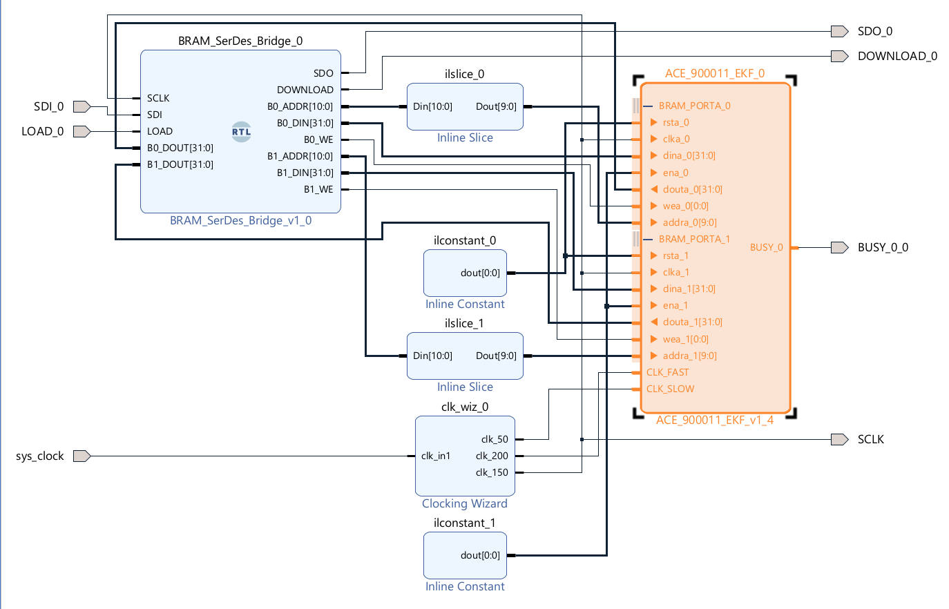
The core is fully controlled through read/write operations on a BRAM (optionally accessible via an AXI BRAM_CONTROLLER). The instantiated BRAMs are 2 True Dual Port memories with port A available to the user and port B managed by the internal Math Engine.
The BRAMs have a width of 32 bits and a depth of 1024 locations. The core uses the first 96 locations (0–95), with the remaining ones completely available for the user via port(s) A (port(s) B are assigned to the internal Math Engine). Port(s) A operates in the user clock domain; Port(s) B operates in the internal engine clock domain.
| IP | ADDR | VARIABLE | DIR | FORMAT | Note |
|---|---|---|---|---|---|
| BRAM_0 | 0 | START_CMD | IN-OUT | BINARY | User needs to set it to 0x1 to start the cycle. The Engine will toggle the LSB at the end of the computation |
| BRAM_0 | 1 | T_curr | IN | FLOAT32 [s] | Time of the measurement |
| BRAM_0 | 2 | px_old/px_new | IN-OUT | FLOAT32 [m] | User writes the last estimated position (ECEF X). The Math Engine overwrites the value at the end of the computation. For consecutive operations on the same target, the new value is stored until the subsequent cycle, avoiding the need to rewrite |
| BRAM_0 | 3 | pz_old/pz_new | IN-OUT | FLOAT32 [m] | User writes the last estimated position (ECEF Z). The Math Engine overwrites the value at the end of the computation. For consecutive operations on the same target, the new value is stored until the subsequent cycle, avoiding the need to rewrite |
| BRAM_0 | 4 | vy_old/vy_new | IN-OUT | FLOAT32 [m/s] | User writes the last estimated velocity (ECEF Y). The Math Engine overwrites the value at the end of the computation. For consecutive operations on the same target, the new value is stored until the subsequent cycle, avoiding the need to rewrite |
| BRAM_0 | 5 | P00_OLD/P00_NEW | IN-OUT | FLOAT32 | P matrix element |
| BRAM_0 | 6 | P02_OLD/P02_NEW | IN-OUT | FLOAT32 | P matrix element |
| BRAM_0 | 7 | P04_OLD/P04_NEW | IN-OUT | FLOAT32 | P matrix element |
| BRAM_0 | 8 | P11_OLD/P11_NEW | IN-OUT | FLOAT32 | P matrix element |
| BRAM_0 | 9 | P13_OLD/P13_NEW | IN-OUT | FLOAT32 | P matrix element |
| BRAM_0 | 10 | P15_OLD/P15_NEW | IN-OUT | FLOAT32 | P matrix element |
| BRAM_0 | 11 | P23_OLD/P23_NEW | IN-OUT | FLOAT32 | P matrix element |
| BRAM_0 | 12 | P25_OLD/P25_NEW | IN-OUT | FLOAT32 | P matrix element |
| BRAM_0 | 13 | P34_OLD/P34_NEW | IN-OUT | FLOAT32 | P matrix element |
| BRAM_0 | 14 | P44_OLD/P44_NEW | IN-OUT | FLOAT32 | P matrix element |
| BRAM_0 | 15 | P55_OLD/P55_NEW | IN-OUT | FLOAT32 | P matrix element |
| BRAM_0 | 16 | Q00 | IN | FLOAT32 | Q matrix element |
| BRAM_0 | 17 | Q02 | IN | FLOAT32 | Q matrix element |
| BRAM_0 | 18 | Q04 | IN | FLOAT32 | Q matrix element |
| BRAM_0 | 19 | Q11 | IN | FLOAT32 | Q matrix element |
| BRAM_0 | 20 | Q13 | IN | FLOAT32 | Q matrix element |
| BRAM_0 | 21 | Q15 | IN | FLOAT32 | Q matrix element |
| BRAM_0 | 22 | Q23 | IN | FLOAT32 | Q matrix element |
| BRAM_0 | 23 | Q25 | IN | FLOAT32 | Q matrix element |
| BRAM_0 | 24 | Q34 | IN | FLOAT32 | Q matrix element |
| BRAM_0 | 25 | Q44 | IN | FLOAT32 | Q matrix element |
| BRAM_0 | 26 | Q55 | IN | FLOAT32 | Q matrix element |
| BRAM_0 | 27 | lat_sens_fx | IN | FIXED POINT [scaled radians] Q2.30 (π=01.0000..., -π=11.0000...) | Latitude of the measuring sensor at time T_curr |
| BRAM_0 | 28 | alt_sens | IN | FLOAT32 [m] | Altitude of the measuring sensor at time T_curr |
| BRAM_0 | 29 | obs_az_fx | IN | FIXED POINT [scaled radians] Q2.30 (π=01.0000..., -π=11.0000...) | Measured azimuth (true bearing) |
| BRAM_0 | 30 | R_RANGE | IN | FLOAT32 [m²] | Range measurement variance |
| BRAM_0 | 31 | R_EL | IN | FLOAT32 [scaled_radians²] | Elevation measurement variance |
| BRAM_0 | 32–91 | DON'T TOUCH | N/A | RESERVED | Internal engine scratchpad registers (do not overwrite during execution) |
| BRAM_0 | 92 | DNA1 | OUT | BINARY | FPGA DNA (MSB) |
| BRAM_0 | 93 | DNA2 | OUT | BINARY | FPGA DNA (LSB) |
| BRAM_0 | 94 | USER_KEY1 | IN | BINARY | LICENSE_KEY (MSB) |
| BRAM_0 | 95 | USER_KEY2 | IN | BINARY | LICENSE_KEY (LSB) |
| BRAM_1 | 0 | T_last | IN | FLOAT32 [s] | Previous measurement time |
| BRAM_1 | 1 | py_old/py_new | IN-OUT | FLOAT32 [m] | User writes the last estimated position (ECEF Y). The Math Engine overwrites the value at the end of the computation. For consecutive operations on the same target, the new value is stored until the subsequent cycle, avoiding the need to rewrite |
| BRAM_1 | 2 | vx_old/vx_new | IN-OUT | FLOAT32 [m/s] | User writes the last estimated velocity (ECEF X). The Math Engine overwrites the value at the end of the computation. For consecutive operations on the same target, the new value is stored until the subsequent cycle, avoiding the need to rewrite |
| BRAM_1 | 3 | vz_old/vz_new | IN-OUT | FLOAT32 [m/s] | User writes the last estimated velocity (ECEF Z). The Math Engine overwrites the value at the end of the computation. For consecutive operations on the same target, the new value is stored until the subsequent cycle, avoiding the need to rewrite |
| BRAM_1 | 4 | P01_OLD/P01_NEW | IN-OUT | FLOAT32 | P matrix element |
| BRAM_1 | 5 | P03_OLD/P03_NEW | IN-OUT | FLOAT32 | P matrix element |
| BRAM_1 | 6 | P05_OLD/P05_NEW | IN-OUT | FLOAT32 | P matrix element |
| BRAM_1 | 7 | P12_OLD/P12_NEW | IN-OUT | FLOAT32 | P matrix element |
| BRAM_1 | 8 | P14_OLD/P14_NEW | IN-OUT | FLOAT32 | P matrix element |
| BRAM_1 | 9 | P22_OLD/P22_NEW | IN-OUT | FLOAT32 | P matrix element |
| BRAM_1 | 10 | P24_OLD/P24_NEW | IN-OUT | FLOAT32 | P matrix element |
| BRAM_1 | 11 | P33_OLD/P33_NEW | IN-OUT | FLOAT32 | P matrix element |
| BRAM_1 | 12 | P35_OLD/P35_NEW | IN-OUT | FLOAT32 | P matrix element |
| BRAM_1 | 13 | P45_OLD/P45_NEW | IN-OUT | FLOAT32 | P matrix element |
| BRAM_1 | 14 | Q01 | IN | FLOAT32 | Q matrix element |
| BRAM_1 | 15 | Q03 | IN | FLOAT32 | Q matrix element |
| BRAM_1 | 16 | Q05 | IN | FLOAT32 | Q matrix element |
| BRAM_1 | 17 | Q12 | IN | FLOAT32 | Q matrix element |
| BRAM_1 | 18 | Q14 | IN | FLOAT32 | Q matrix element |
| BRAM_1 | 19 | Q22 | IN | FLOAT32 | Q matrix element |
| BRAM_1 | 20 | Q24 | IN | FLOAT32 | Q matrix element |
| BRAM_1 | 21 | Q33 | IN | FLOAT32 | Q matrix element |
| BRAM_1 | 22 | Q35 | IN | FLOAT32 | Q matrix element |
| BRAM_1 | 23 | Q45 | IN | FLOAT32 | Q matrix element |
| BRAM_1 | 24 | lon_sens_fx | IN | FIXED POINT [scaled radians] Q2.30 (π=01.0000..., -π=11.0000...) | Longitude of the measuring sensor at time T_curr |
| BRAM_1 | 25 | obs_range | IN | FLOAT32 [m] | Measured Range |
| BRAM_1 | 26 | obs_el_fx | IN | FIXED POINT [scaled radians] Q2.30 (π=01.0000..., -π=11.0000...) | Measured True Elevation |
| BRAM_1 | 27 | R_AZ | IN | FLOAT32 [scaled_radians²] | Bearing measurement variance |
| BRAM_1 | 28–95 | DON'T TOUCH | N/A | RESERVED | Internal engine scratchpad registers (do not overwrite during execution) |
In addition to the BRAM interface, the core exposes:
CLK_SLOW is used for the initialization and for the access to the DNA reader primitive (50 MHz)CLK_FAST is used to drive the internal computation engine (Max Frequency: 200 MHz)BUSY pin that, when set to high, signals when the core is executing the initialization or its main function.
The core, at power-up, performs an initialization sequence that lasts (with CLK_SLOW @ 50 MHz) less than 5,000 ns.
When the initialization is complete, the BRAM is populated with the DNA of the FPGA (see Memory Map).
Once the initialization is complete, the user may load the BRAM in accordance with the input reported in the Memory Map and, finally, set the START_CMD to 0x1.
The results are written in BRAM, in accordance with the memory map, after exactly 1,536 clock cycles. The end of execution is communicated by the core by setting the START_CMD to 0x0 and via the BUSY pin (BUSY=0 indicates the core is in the IDLE state, ready for the new execution).
When the START_CMD is asserted, the core performs the entire computation. Execution cannot be stopped. Writing on the BRAM first 96 addresses during the execution will produce undefined results and it is not supported. The execution will always complete in the specified 1,536 clock cycle window.
Note: if the USER_KEY is not correct, the core terminates in the specified timeframe, but produces unpredictable results.
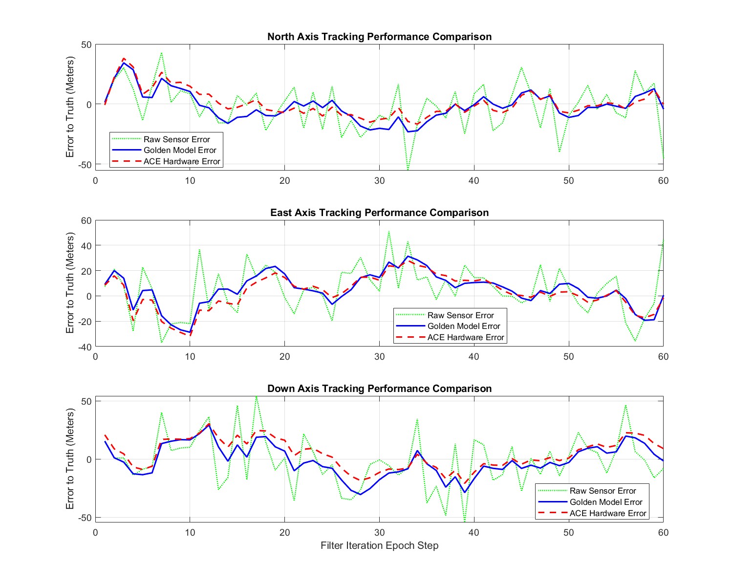
The ACE90011 hardware core undergoes rigorous validation via a "Math-to-Silicon" functional pipeline. Performance results are verified using an explicit dual-filter co-simulation testbench framework running alongside a single-precision software Golden Model. Both tracking profiles process identical noisy, asynchronous multi-sensor spherical inputs (Range, Azimuth, Elevation) generated by a target trajectory. For verification consistency, both filter instances are deliberately initialized with an identical state displacement offset in local coordinates ($[1000, -2000, -200]$ meters in the NED frame) to test convergence capabilities and baseline recovery.
Hardware-in-the-loop and post-placement testbench validation tracks exact register outputs inside the dual BRAM memory structure across active filtering epochs. The validation script continuously audits base-10 single-precision IEEE-754 hardware conversions directly against the modeling equations. Crucial internal parameters—such as the Innovation Covariance matrix determinant ($\det(S)$), inverted elements ($S^{-1}_{xx}$), state error covariances ($P_{yz}$), and corrected state vectors—confirm exact architectural alignment with zero numerical divergence.
An extract of the simulated data is reported in Table 2.
| Filter Epoch | Parameter Description | BRAM Target Address | Hexadecimal Token Value | Decoded Physical Metric |
|---|---|---|---|---|
| STAGE 1 ($t = 1.5\text{ s}$) | Estimated ECEF X Position (px_new) | BRAM0 / Addr 02 | 0x4A7941DC | 4,083,830.00 m |
| Innovation Covariance Determinant (DetS) | BRAM0 / Addr 76 | 0x3718A5A4 | $9.09847 \times 10^{-6}$ | |
| Cross Error Covariance Element (P01) | BRAM1 / Addr 04 | 0x43458178 | 197.506 | |
| Inverted Innovation Matrix Scalar (si00) | BRAM1 / Addr 71 | 0x3800A8CB | $3.06748 \times 10^{-5}$ | |
| STAGE 10 ($t = 15.0\text{ s}$) | Estimated ECEF Z Position (pz_new) | BRAM0 / Addr 03 | 0x4A949A96 | 4,869,450.00 m |
| Estimated ECEF X Velocity (vx_new) | BRAM1 / Addr 02 | 0xC1128553 | -9.15755 m/s | |
| STAGE 30 ($t = 45.0\text{ s}$) | Innovation Covariance Determinant (DetS) | BRAM0 / Addr 76 | 0x2DED44DF | $2.69744 \times 10^{-11}$ |
| Estimated ECEF Y Velocity (vy_new) | BRAM0 / Addr 04 | 0x409C6AA4 | 4.88802 m/s | |
| STAGE 60 ($t = 90.0\text{ s}$) | Estimated ECEF Y Position (py_new) | BRAM1 / Addr 01 | 0x48B38BD2 | 367,711.00 m |
| Cross Error Covariance Element (P01) | BRAM1 / Addr 04 | 0x42536D7B | 52.8569 |
To provide an informative, system-level interpretation of filter accuracy, absolute ECEF state estimation vectors are transformed into the local North-East-Down (NED) frame relative to the moving sensor platform position. This transformation uses Bowring's closed-form geodetic equations mapped into a localized Direction Cosine Matrix.
Tracking performance analysis isolates individual spatial and velocity components against real ground truth target data. The architectural choices result in unique tracking behaviors:
The structural integrity of the analytic matrix inversion engine (implemented inside the DSP arithmetic pipelines via Cramer's Rule) is heavily bound to the Innovation Matrix determinant ($\det(S)$).
During initial track acquisition at Stage 1, the high estimation variance results in a well-conditioned determinant value ($\det(S) = 9.09847 \times 10^{-6}$).
As the state updates lock onto the steady-state target flight path, the covariance fields decay uniformly. By Stage 60, the hardware matrix loops handle extremely tight innovation metrics down to $\det(S) \approx 2.69744 \times 10^{-11}$ without underflow clipping, showing robust numerical stability under high-dynamic scenarios.
ACE90011 is delivered as a pre‑packaged Vivado IP core, ready for integration through the AMD/Xilinx IP Catalog.
Each licensed core includes:
USER_KEY file for license activation
ACE provides a USER_KEY value (64 bits) for FPGA Serial Number (DNA for AMD/Xilinx). The keys are delivered in a simple CSV file (a template is reported below):
DNA_HEX,AUTHORIZATION_KEY
0011223344556677,C303E222F7D44C5B
ABCDE1234567890F,A2A3A3114194ED74
5566778899AABBCC,94C023F594AA6F63
DEADBEEF12345678,F40237F85DFB6F2A
00123456789ABCDE,E8ACBBDBFCF3ACB7
...............,.................
The user may store the file with all the SN/licenses and select the key to load after reading the SN of the FPGA from the BRAM_PORTA interface of the ACE90011 core.
The envisioned process is the following:
BRAM_PORTA interface exposed by the ACE90011 core.USER_KEY corresponding to the FPGA SN in the ACE provided USER_KEY file.USER_KEY via the BRAM_PORTA interface exposed by the ACE90011 core.
The keys are generated on customer order. In simulation, a demo DNA is used and the corresponding USER_KEY is provided in the file for a seamless experience.
Pricing is provided directly by ACE based on:
Customers may request a quotation by providing their expected deployment profile and FPGA device list.
Data Privacy note: By contacting us via email, you agree that we will use your provided contact details and mathematical specifications solely to evaluate project feasibility during our early-access phase. We do not sell or share your personal information with third parties. We may use standard web analytics tools to monitor basic, aggregated website traffic to improve our site performance.